Making your Raspberry Pi work as Stratum One requires some kind of reference clock like GPS/GNSS. You can either buy a HAT or find your solder iron and modify a GPS-drone puck yourself.
Your GPS-puck MUST be able to convert from 5.0 Volt to 3.3. in this setup as we want 3 Volt on the TXD and RXD pins only.
How to wire the RasPi?
From the very start I never had any smart connections but i big pile of old RS-232 serial interfaces from a PC. I simply cut the cable in two half and the sockets goes nearly directly into my RasPi pins 1 to 2 to 10.
On some connectors, pin 10 is blocked by plastic. This means you can’t make it fit on a RasPi.
Install your physical GPS-unit on cabling as something like this:
RasPi Pins
- Pin 2 = Power +5V (or Pin 4) (red on GPS-puck)
(UART pin 9). (if you need 3.3V go for pin 1 or pin 17 But you cannot use the rs-232 9 wire as your ether loose 3.3 VOlt or on pin1 or RXD on pin 10. - Pin 9 = GND (or pin 6) (black on GPS-puck
(UART pin 2). - Pin 7 = PPS input from GPS-receiver (GPIO4 GPCLK0, max 3.3. Volt) (white on GPS-puck)
(UART pin 4) - Pin 10 = NMEA input from GPS receiver (UART RXD GPIO 15) (Yellow from GPS-puck)
(UART pin 1) - Pin 8 = Programming (UART TXD GPIO 14) (Green from GPS-Puck) – I use it now and then for soft-reset or programming via the util #gpsctl
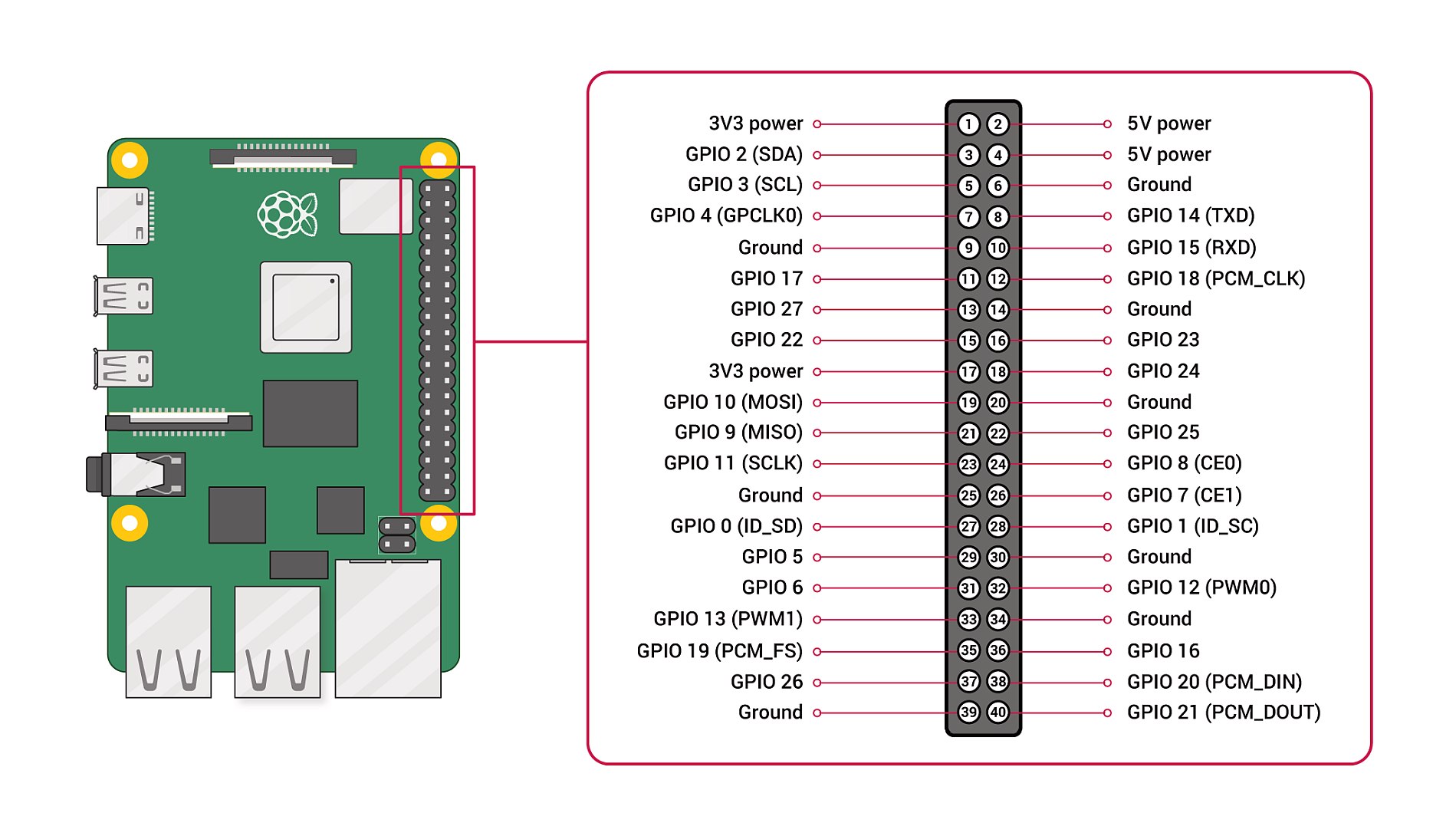
(Assumed UART connector pin 1 red wire at RasPi pin 10)
Ref: https://www.raspberrypi.com/documentation/computers/raspberry-pi.html
Puck wire and GNSS pin layout
Original Puck:
- Black GND
- Red VCC
- Yellow TXD
- Green RXD
- Blue SCL
- White SDA
Modified to:
NEO-M8N RASPI
- Black GND Pin 9 (or 6) (GND)
- Red VCC Pin 2 (+5 Volt)
- Yellow TXD Pin 10 (UART RXD)
- Green RXD (not in use) Pin 8 (UART TXD)
- Blue SCL (not in use) Pin 5 (?SCL1)
- White ORG Modified to PPS by resoldering the wire to NEO-M8N pin 3 Pin 7 (GPIO4)
- White New SDA (on this model soldered extra wire. Not in use) Pin 3 (?SDA1)
NEO M8N N-M8030 2019 model RASPI
- Red VCC Pin 2 (+5 Volt)
- Black GND Pin 9 (GND)
- Orange SCL
- White SDA
- Green TXD Pin 10 (UART RXD)
- Yellow RXD Pin 8 (UART TXD)
- White NEW PPS Pin 7 (GPIO 4)
Wirring on NAZE mini GPS
- Black GND Pin 9 or 6
- Red VCC Pin 1 (x3.3 Volt)
- Blue RXD Pin 8 (UARS TXD)
- Orange TXD Pin 10 (UART RXD)
- Yellow PPS (self soldered) Pin 7 (GPIO4
This is all on your own responsibility and you have to control the colours and pins of the GNSS-reciever. I have seen two of the same pucks that should fit directly to a drone but the colours of wiring was reversed. Disaster if you power on such receiver as it will burn it up due to 5 Volt reverse on 3.3 Volt ttl pins. It have the same effect like a surge.
Starting your GPS might requires long time for very first fix as its needs to read-in a complete almanac telling where the receiver can find a specific GNSS satellite at a specific time. Up to 30-40 min on very poor satellite connection is seen. Speed up by making sure you free visibility to the sky from all compass directions.
Overview of time satellite GNSS
GNSS = Global Navbigation Satellite System is the officiel umbralley term for positions satellites and more and more used for Stratumn One time servers with satellite reference.
GPS = Global Position system. American.
GAL = Galileo, European GNSS. The name derives from the Italian astronomer Galileo Galilei.
BDS = BeiDou Navigation Satellite System, Republic of China.
GLONASS = Globalnaya Navigazionnaya Sputnikovaya Sistema, or Global Navigation Satellite System, Russia.
IRNSS = Indian Regional Navigation Satellite System, Indian.
QZSS = Quasi-Zenith Satellite System, Japan.
On modern GNSS-receivers like uBlox 8 and forward you might be capable to receive signal for these constellations.
If you got no smoke and LED-are flashing the right way its time to add Chrony and GPSD software if haven’t done that.